









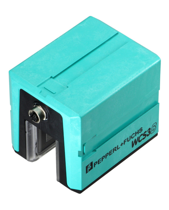

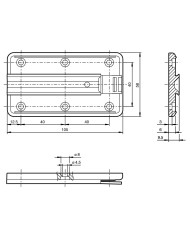

WCS3B-LS710S EtherCAT Read Head
Ask for price
Read head with EtherCAT interface
- EtherCAT interface
- Non-contact, absolute position encoder
- Automatic detection of dirt accumulation
- Speed transfer
Description
Product Details
The WCS position encoding system consists of two main components:
Code Rail
The code rail carries information for the absolute code. The code rail is routed parallel to the track for the material handling equipment and thus assigns a unique position to every point on the track. It is possible to route the code rail at points only where positioning is required. The system allows the code rail to be routed along curves and allows branches to be created. The code rail is built to order and delivered in a bundle. Unless otherwise ordered, the code rail always starts with position value 0 and ends with a maximum position according to the ordered length in meters. The length of a code rail segment ranges from 0 to a maximum total length of 314.573 m (WCS3) or from 0 to a maximum total length of 327 m (WCS2).
Spacers can also be ordered for repair purposes or specific applications, stating the start or end position of the desired section and the desired length in meters.
For identification applications ID-pads are available as short code rail sections, with a length of between 250 mm and 264 mm and a unique identification number.
Read Head
The U-shaped read head scans the code rail photoelectronically without touching it. The read head detects a new position value every 0.8 mm (WCS3) or 0.833 mm (WCS2).
This results in the following data:
| WCS2B | WCS3B | |
| Resolution |
± 0.42 mm 1200 pos./m |
± 0.40 mm 1250 pos./m |
| Movement speed [vmax] | 12.5 m/s | 12.5 m/s |
| Y axis (tolerance) | ± 5 mm | ± 15.5 mm |
| X axis (tolerance) | ± 5 mm | ± 14 mm |
After insertion into the code rail, the read head determines a highly accurate position value without reference or delay. The code rail can be scanned at very high speeds. The scanning can be reproduced, is reliable, and is independent of temperature fluctuations.
The position value, movement speed, and error codes such as the contamination detection or the “OUT” message can be transmitted directly from the read head to the control panel via a communication interface. There are a number of types of interfaces available in the WCS3 read head to achieve this, such as RS-485, SSI, CANopen, PROFINET, and EtherNet/IP.
There is a wide range of interface modules available for connecting to other interfaces:
- PROFINET
- PROFIBUS DP
- EtherNet/IP
- EtherCAT
- DeviceNet
- CANopen
Each interface module can simultaneously accommodate up to four read heads with an RS-485 interface and address each separately. This makes it easy to extend your plant at a later stage.
In addition to automatic contamination detection, there are other optional extensions for the WCS read head. The options are indicated in the type code with the corresponding letter:
| WCS2B and WCS3B | |
| H | Integrated heating element for an extended outside temperature range as low as -40 °C. |
| WCS3B | |
| D | Integrated display with a seven-segment display for position and diagnostic information. |
| E | Read head with Extended option for long distances of up to 629.146 meters. |
| O | Outdoor protective enclosure with degree of protection IP69 for outdoor use. |
| S | Switching output for signaling when a limit speed is exceeded. |
Technical data
General specifications
| Sampling rate | 1.5 ms | |
| Passage speed | v | ≤ 12.5 m/s |
| Measuring length | max. 314.5 m | |
| Free tolerances to code rail |
horizontal: 31 mm ( ± 15.5 mm )
vertical: 28 mm ( ± 14 mm ) |
|
| Resolution | ± 0.4 mm (1,250 positions/m) |
Functional safety related parameters
| MTTFd | 160 a | |
| Mission Time (TM) | 20 a | |
| Diagnostic Coverage (DC) | 0 % |
Indicators/operating means
| LED indication |
status indication
green: code rail detected, normal function red: system error flashing red: no code rail detected |
|
| LED ERROR |
error status (red)
see manual for coding |
|
| LED RUN |
off: init
flashing (green): pre-operational single flash (green): safe-operational on (green): operational |
|
| LED Link/Act | port status (green) |
Electrical specifications
| Operating voltage | UB | 10 … 30 V DC |
| Power consumption | P0 | 6 W |
Interface
| Interface type | Ethernet; 100 BASE-TX | |
| Data output code | binary code | |
| Protocol | EtherCAT | |
| Transfer rate | 100 MBit/s |
Output
| Output velocity |
switching output
short-circuit protected |
|
| Switching voltage | Operating voltage | |
| Load current | max. 25 mA |
Standard conformity
| Emitted interference | EN 61000-6-4:2007+A1:2011 | |
| Noise immunity | EN 61000-6-2:2005 | |
| Shock resistance | EN 60068-2-27:2009 | |
| Vibration resistance | EN 60068-2-6:2008 |
Approvals and certificates
| CSA approval |
cCSAus Certified, General Purpose
Class 2 power source |
|
| CCC approval | CCC approval / marking not required for products rated ≤36 V |
Ambient conditions
| Operating temperature | 0 … 60 °C (32 … 140 °F) | |
| Storage temperature | -40 … 85 °C (-40 … 185 °F) | |
| Relative humidity | 90 %, noncondensing |
Mechanical specifications
| Connection type | 8-pin, M12 x 1 connector socket, Y-coded | ||||||||||
| Cable gland | Max. tightening torque of the cap nut: ≤ 0.4 Nm | ||||||||||
| Degree of protection | IP54 | ||||||||||
| Material | |||||||||||
|
|||||||||||
| Mass | 500 g | ||||||||||
| Dimensions | |||||||||||
|
|||||||||||
General information
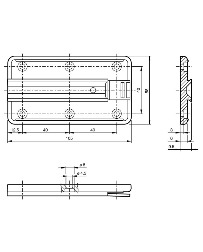
| Ordering information | Mounting plate included with delivery |