












HiC2025 SMART Transmitter Power Supply
Ask for price
- 1-channel isolated barrier
- 24 V DC supply (bus powered)
- Input for 2-wire SMART transmitters and current sources
- Output for 4 mA … 20 mA or 1 V … 5 V
- Low power dissipation
- Up to SIL 2 (SC 3) acc. to IEC/EN 61508
Description
Product Details
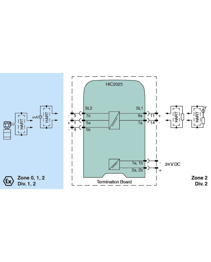
This isolated barrier is used for intrinsic safety applications.
The device supplies 2-wire transmitters in the hazardous area, and can also be used with current sources.
It transfers the analog input signal to the safe area as an isolated current value.
Bi-directional communication is supported for SMART transmitters that use current modulation to transmit data and voltage modulation to receive data.
The output is selected as a current source, current sink, or voltage source via DIP switches.
This device mounts on a HiC Termination Board.
Technical data
General specifications
| Signal type | Analog input |
Functional safety related parameters
| Safety Integrity Level (SIL) | SIL 2 | |
| Systematic capability (SC) | SC 3 |
Supply
| Connection | SL1: 1a, 1b(-); 2a, 2b(+) | |
| Rated voltage | Ur | 19 … 30 V DC bus powered via Termination Board |
| Ripple | ≤ 10 % | |
| Rated current | Ir | ≤ 45 mA at 24 V and 20 mA source mode output |
| Power dissipation | ≤ 800 mW | |
| Power consumption | ≤ 1.1 W |
Input
| Connection side | field side | |
| Connection | SL2: 5a(+), 1b(-); 5a(+), 5b(-) | |
| Input signal | 4 … 20 mA limited to approx. 26 mA | |
| Voltage drop | approx. 5 V on SL2: 5a(+), 1b(-) | |
| Available voltage | ≥ 15 V at 20 mA, ≥ 18 V at 4 mA on SL2: 5a(+), 5b(-) |
Output
| Connection side | control side | |
| Connection | SL1: 8a(+), 7a(-) | |
| Load | 0 … 350 Ω (source mode) | |
| Output signal |
source mode: 4 … 20 mA or 1 … 5 V
(internal resistor: 250 Ω, 0.1 %)
sink mode: 4 … 20 mA, operating voltage 10 … 30 V For additional internal or external loads the voltage drop has to be considered, e. g. 250 Ω x 20 mA = 5 V. |
|
| Ripple | 20 mVrms |
Transfer characteristics
| Deviation |
at 20 °C (68 °F)
< 0.1 % of full scale, incl. non-linearity and hysteresis (source mode and sink mode 4 … 20 mA) ≤ ± 0.2 % incl. non-linearity and hysteresis (source mode 1 … 5 V) |
||||
|
|||||
| Frequency range |
field side into the control side:
bandwidth with 0.5 Vpp signal 0 … 3 kHz (-3 dB)
control side into the field side: bandwidth with 0.5 Vpp signal 0 … 3 kHz (-3 dB) |
||||
| Settling time | ≤ 50 ms | ||||
| Rise time/fall time | ≤ 10 ms | ||||
Galvanic isolation
| Input/Output | safe electrical isolation acc. to IEC/EN 60079-11, voltage peak value 375 V | |
| Input/power supply | safe electrical isolation acc. to IEC/EN 60079-11, voltage peak value 375 V | |
| Output/power supply | basic insulation according to IEC/EN 61010-1, rated insulation voltage 60 Veff |
Indicators/settings
| Display elements | LED | |
| Control elements | DIP switch | |
| Factory setting | output: current source | |
| Configuration | via DIP switches | |
| Labeling | space for labeling at the front |
Directive conformity
| Electromagnetic compatibility | |||||
|
|||||
Conformity
| Electromagnetic compatibility |
NE 21:2017
EN 61326-3-2:2018 For further information see system description. |
|
| Degree of protection | IEC 60529:2001 | |
| Protection against electrical shock | UL 61010-1:2018 |
Ambient conditions
| Ambient temperature | -40 … 70 °C (-40 … 158 °F) |
Mechanical specifications
| Degree of protection | IP20 | |
| Mass | approx. 100 g | |
| Dimensions | 12.5 x 106 x 128 mm (0.5 x 4.2 x 5.1 inch) (W x H x D) | |
| Mounting | on termination board | |
| Coding |
pin 1 and 3 trimmed
For further information see system description. |
Data for application in connection with hazardous areas
| EU-type examination certificate | CESI 06 ATEX 017 | |||||||||||||||||||||||||
|
||||||||||||||||||||||||||
| Supply | ||||||||||||||||||||||||||
|
||||||||||||||||||||||||||
| Equipment | SL2: 5a(+), 5b(-) | |||||||||||||||||||||||||
|
||||||||||||||||||||||||||
| Equipment | SL2: 5a(+), 1b(-) | |||||||||||||||||||||||||
|
||||||||||||||||||||||||||
| Certificate | CESI 19 ATEX 027 X | |||||||||||||||||||||||||
|
||||||||||||||||||||||||||
| Directive conformity | ||||||||||||||||||||||||||
|
||||||||||||||||||||||||||
International approvals
| FM approval | ||||||||
|
||||||||
| UL approval | E106378 | |||||||
|
||||||||
| IECEx approval | ||||||||
|
||||||||
General information
| Supplementary information | Observe the certificates, declarations of conformity, instruction manuals, and manuals where applicable. For information see www.pepperl-fuchs.com. |