









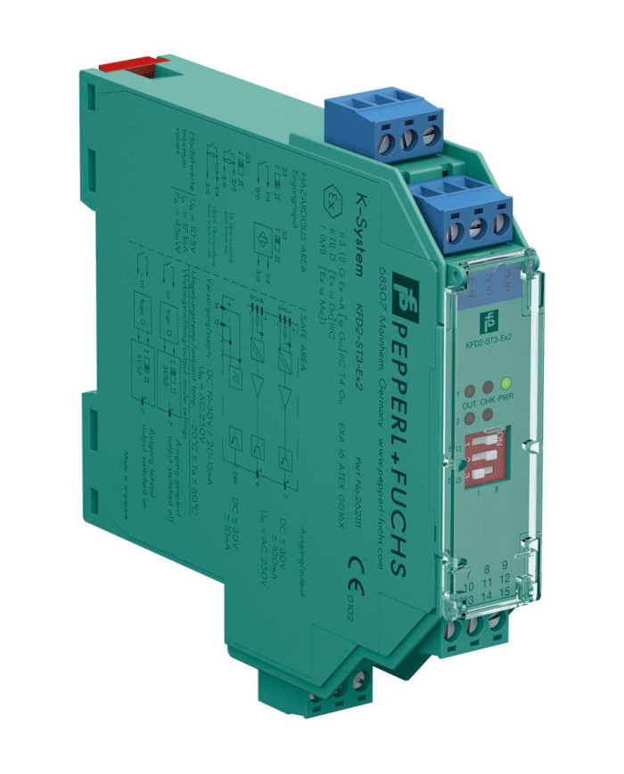

KFD2-ST3-Ex2 Switch Amplifier
Ask for price
- 2-channel isolated barrier
- 24 V DC supply (Power Rail)
- Dry contact or NAMUR inputs
- Active transistor output
- Line fault detection (LFD)
- Reversible mode of operation
- Up to SIL 2 (SC 3) acc. to IEC/EN 61508
Description
Product Details
This isolated barrier is used for intrinsic safety applications.
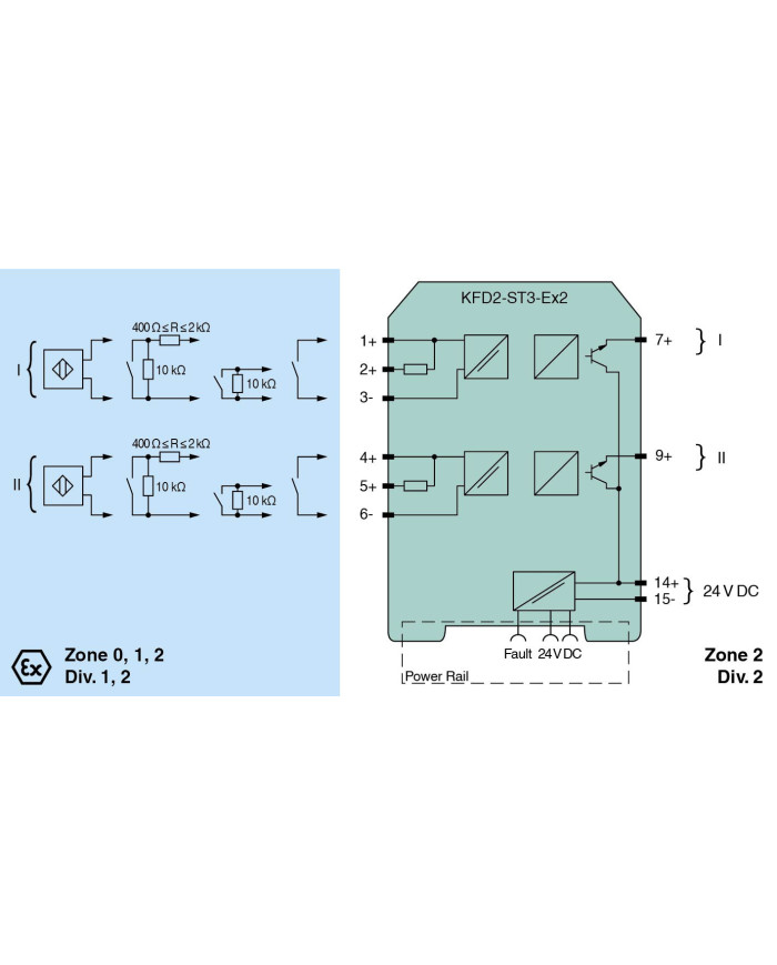
The device transfers digital signals (NAMUR sensors or dry contacts) from a hazardous area to a safe area.
Each input controls an active transistor output.
Via switches the mode of operation can be reversed and the line fault detection can be switched off.
A fault is signalized by LEDs acc. to NAMUR NE44 and a separate collective error message output.
Technical data
General specifications
| Signal type | Digital Input |
Functional safety related parameters
| Safety Integrity Level (SIL) | SIL 2 | |
| Systematic capability (SC) | SC 3 |
Supply
| Connection | Power Rail or terminals 14+, 15- | |
| Rated voltage | Ur | 19 … 30 V DC |
| Ripple | ≤ 10 % | |
| Rated current | Ir | 20 … 15 mA + Iout |
| Power dissipation | ≤ 900 mW including maximum power dissipation in the output |
Input
| Connection side | field side | |
| Connection | terminals 1+, 2+, 3-; 4+, 5+, 6- | |
| Rated values | acc. to EN 60947-5-6 (NAMUR) | |
| Open circuit voltage/short-circuit current | approx. 10 V DC / approx. 8 mA | |
| Switching point/switching hysteresis | 1.2 … 2.1 mA / approx. 0.2 mA | |
| Line fault detection | breakage I ≤ 0.1 mA, short-circuit I ≥ 6.5 mA | |
| Pulse/Pause ratio | min. 100 µs / min. 100 µs |
Output
| Connection side | control side | |
| Connection | output I: terminal 7+ ; output II: terminal 9+ | |
| Rated voltage | Ur | 30 V DC |
| Rated current | Ir | 100 mA |
| Response time | ≤ 200 µs | |
| Signal level |
1-signal: (supply voltage) - 3 V max. for 100 mA
0-signal: blocked output (off-state current ≤ 10 µA) |
|
| Output I | signal ; Transistor | |
| Output II | signal ; Transistor | |
| Collective error message | Power Rail |
Transfer characteristics
| Switching frequency | ≤ 5 kHz |
Galvanic isolation
| Input/Output | reinforced insulation according to IEC/EN 61010-1, rated insulation voltage 300 Veff | |
| Input/power supply | reinforced insulation according to IEC/EN 61010-1, rated insulation voltage 300 Veff |
Indicators/settings
| Display elements | LEDs | |
| Control elements | DIP switch | |
| Configuration | via DIP switches | |
| Labeling | space for labeling at the front |
Directive conformity
| Electromagnetic compatibility | |||||
|
|||||
Conformity
| Electromagnetic compatibility | NE 21:2012, EN 61326-3-2:2008 | |
| Degree of protection | IEC 60529:2001 | |
| Input | EN 60947-5-6:2000 |
Ambient conditions
| Ambient temperature | -20 … 60 °C (-4 … 140 °F) |
Mechanical specifications
| Degree of protection | IP20 | ||||||||||
| Connection | screw terminals | ||||||||||
| Mass | approx. 150 g | ||||||||||
| Dimensions | 20 x 119 x 115 mm (0.8 x 4.7 x 4.5 inch) (W x H x D), housing type B2 | ||||||||||
|
|||||||||||
| Mounting | on 35 mm DIN mounting rail acc. to EN 60715:2001 | ||||||||||
Data for application in connection with hazardous areas
| EU-type examination certificate | EXA 16 ATEX 0016 X | ||||||||||||||||
|
|||||||||||||||||
| Supply | |||||||||||||||||
|
|||||||||||||||||
| Output | |||||||||||||||||
|
|||||||||||||||||
| Galvanic isolation | |||||||||||||||||
|
|||||||||||||||||
| Directive conformity | |||||||||||||||||
|
|||||||||||||||||
International approvals
| UL approval | E106378 | |||||||
|
||||||||
| IECEx approval | ||||||||
|
||||||||
General information
| Supplementary information | Observe the certificates, declarations of conformity, instruction manuals, and manuals where applicable. For information see www.pepperl-fuchs.com. |