









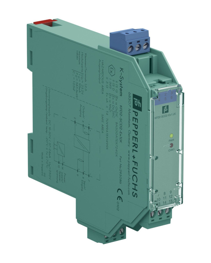


KFD2-SCD2-Ex1.LK SMART Current Driver
Ask for price
- 1-channel isolated barrier
- 24 V DC supply (power rail)
- Current output up to 650 Ω load
- HART-IP and valve positioner
- Line fault detection (LFD)
- Accuracy 0.1 %
- Up to SIL 2 (SC 3) acc. to IEC/EN 61508
Description
Product Details
This isolated barrier is used for intrinsic safety applications.
The device drives SMART I/P converters, electrical valves, and positioners in hazardous areas.
Digital signals are superimposed on the analog values at the field side or control side and are transferred bi-directionally.
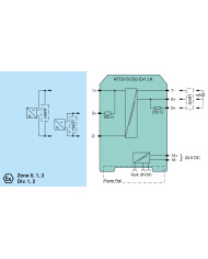
Current transferred across the DC/DC converter is repeated at terminals 1 and 2. Terminals 2 and 3 are used when no short circuit detection is required.
An open or short field circuit presents a high impedance to the control side to allow alarm conditions to be monitored by the control system.
If the HART communication resistance in the loop is too low, the internal resistance can be used.
Test sockets for the connection of HART communicators are integrated into the terminals of the device.
A fault is signalized by LEDs and a separate collective error message output.
Technical data
General specifications
| Signal type | Analog output |
Functional safety related parameters
| Safety Integrity Level (SIL) | SIL 2 | |
| Systematic capability (SC) | SC 3 |
Supply
| Connection | Power Rail or terminals 14+, 15- | |
| Rated voltage | Ur | 19 … 30 V DC |
| Ripple | ≤ 10 % | |
| Rated current | Ir | ≤ 30 mA at 24 V |
| Power dissipation | ≤ 600 mW at 20 mA and 500 Ω load | |
| Power consumption | ≤ 700 mW |
Input
| Connection side | control side | |
| Connection | terminals 7-, 8+, (9+) | |
| Input signal | 4 … 20 mA, limited to approx. 30 mA | |
| Input voltage | open loop voltage of the control system ≤ 30 V | |
| Voltage drop | approx. 6 V at 20 mA | |
| Input resistance |
field wiring open circuit : > 100 kΩ
field wiring < 50 Ω : > 100 kΩ when using terminals 1 and 2 |
Output
| Connection side | field side | |
| Connection |
terminals 1+, 2-
terminals 3+, 2- (no short circuit detection) |
|
| Voltage | ≥ 13 V at 20 mA | |
| Current | 4 … 20 mA | |
| Load |
100 … 650 Ω, for terminals 1, 2
0 … 550 Ω, for terminals 2, 3 |
|
| Ripple | 20 mV rms | |
| Line fault detection | breakage, load > 100 kΩ, short-circuit, load < 50 Ω |
Fault indication output
| Output type | open collector transistor (internal fault bus) |
Transfer characteristics
| Deviation |
at 20 °C (68 °F), 4 … 20 mA
< 0.1 % of full scale, incl. non-linearity and hysteresis |
||||
|
|||||
| Frequency range |
field side into the control side: bandwidth with 0.5 Vpp signal 0 … 3 kHz (-3 dB)
control side into the field side: bandwidth with 0.5 Vpp signal 0 … 3 kHz (-3 dB) |
||||
| Rise time | 10 to 90 % ≤ 10 ms | ||||
Galvanic isolation
| Input/Output | basic insulation according to IEC/EN 61010-1, rated insulation voltage 300 Veff | |
| Input/power supply | basic insulation according to IEC/EN 61010-1, rated insulation voltage 300 Veff | |
| Output/power supply | reinforced insulation according to IEC/EN 61010-1, rated insulation voltage 300 Veff |
Indicators/settings
| Display elements | LEDs | |
| Labeling | space for adhesive label at the front |
Directive conformity
| Electromagnetic compatibility | |||||
|
|||||
Conformity
| Electromagnetic compatibility |
NE 21:2017
EN 61326-3-2:2018 |
|
| Degree of protection | IEC 60529 | |
| Protection against electrical shock | UL 61010-1:2012 |
Ambient conditions
| Ambient temperature | -40 … 70 °C (-40 … 158 °F) |
Mechanical specifications
| Degree of protection | IP20 | |
| Connection | screw terminals | |
| Mass | approx. 115 g | |
| Dimensions | 20 x 124 x 115 mm (0.8 x 4.9 x 4.5 inch) (W x H x D), housing type B2 | |
| Mounting | on 35 mm DIN mounting rail acc. to EN 60715:2001 |
Data for application in connection with hazardous areas
| EU-type examination certificate | BAS 00 ATEX 7240 X | ||||||||||||||||||||||
|
|||||||||||||||||||||||
| Supply | |||||||||||||||||||||||
|
|||||||||||||||||||||||
| Input | |||||||||||||||||||||||
|
|||||||||||||||||||||||
| Certificate | FIDI 22 ATEX 0002 X | ||||||||||||||||||||||
|
|||||||||||||||||||||||
| Galvanic isolation | |||||||||||||||||||||||
|
|||||||||||||||||||||||
| Directive conformity | |||||||||||||||||||||||
|
|||||||||||||||||||||||
International approvals
| UL approval | E106378 | |||||||
|
||||||||
| IECEx approval | ||||||||
|
||||||||
General information
| Supplementary information | Observe the certificates, declarations of conformity, instruction manuals, and manuals where applicable. For information see www.pepperl-fuchs.com. |