









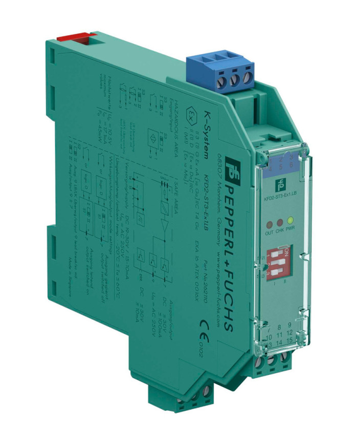

KFD2-ST3-Ex1.LB Switch Amplifier
Ask for price
- 1-channel isolated barrier
- 24 V DC supply (power rail)
- Dry contact or NAMUR inputs
- 2 active transistor outputs
- Usable as signal splitter (1 input and 2 outputs)
- Reversible mode of operation
- Line fault detection (LFD)
- Up to SIL 2 (SC 3) acc. to IEC/EN 61508
Description
Product Details
This isolated barrier is used for intrinsic safety applications.
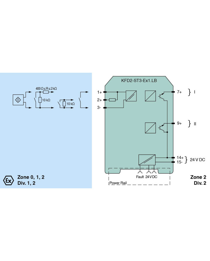
The device transfers digital signals (NAMUR sensors or dry contacts) from a hazardous area to a safe area.
The input controls two active transistor outputs.
Via switches the mode of operation can be reversed and the line fault detection can be switched off.
Via switch the function of the second output can be defined as a signal output or an error output.
A fault is signalized by LEDs acc. to NAMUR NE44 and a separate collective error message output.
Technical data
General specifications
| Signal type | Digital Input |
Functional safety related parameters
| Safety Integrity Level (SIL) | SIL 2 | |
| Systematic capability (SC) | SC 3 |
Supply
| Connection | Power Rail or terminals 14+, 15- | |
| Rated voltage | Ur | 19 … 30 V DC |
| Ripple | ≤ 10 % | |
| Rated current | Ir | 15 … 10 mA + Iout |
| Power dissipation | ≤ 800 mW including maximum power dissipation in the output |
Input
| Connection side | field side | |
| Connection | terminals 1+, 2+, 3- | |
| Rated values | acc. to EN 60947-5-6 (NAMUR), see manual for electrical data | |
| Open circuit voltage/short-circuit current | approx. 10 V DC / approx. 8 mA | |
| Switching point/switching hysteresis | 1.2 … 2.1 mA / approx. 0.2 mA | |
| Line fault detection | breakage I ≤ 0.1 mA , short-circuit I ≥ 6.5 mA | |
| Pulse/Pause ratio | min. 100 µs / min. 100 µs |
Output
| Connection side | control side | |
| Connection | output I: terminal 7+ ; output II: terminal 9+ | |
| Rated voltage | Ur | 30 V DC |
| Rated current | Ir | 100 mA |
| Response time | ≤ 200 µs | |
| Signal level |
1-signal: (supply voltage) - 3 V max. for 100 mA
0-signal: blocked output (off-state current ≤ 10 µA) |
|
| Output I | signal ; Transistor | |
| Output II | signal or fault message ; Transistor | |
| Collective error message | Power Rail |
Transfer characteristics
| Switching frequency | ≤ 5 kHz |
Galvanic isolation
| Input/Output | reinforced insulation according to IEC/EN 61010-1, rated insulation voltage 300 Veff | |
| Input/power supply | reinforced insulation according to IEC/EN 61010-1, rated insulation voltage 300 Veff |
Indicators/settings
| Display elements | LEDs | |
| Control elements | DIP switch | |
| Configuration | via DIP switches | |
| Labeling | space for labeling at the front |
Directive conformity
| Electromagnetic compatibility | |||||
|
|||||
Conformity
| Electromagnetic compatibility | NE 21:2012, EN 61326-3-2:2008 | |
| Degree of protection | IEC 60529:2001 | |
| Input | EN 60947-5-6:2000 |
Ambient conditions
| Ambient temperature | -20 … 60 °C (-4 … 140 °F) |
Mechanical specifications
| Degree of protection | IP20 | ||||||||||
| Connection | screw terminals | ||||||||||
| Mass | approx. 150 g | ||||||||||
| Dimensions | 20 x 119 x 115 mm (0.8 x 4.7 x 4.5 inch) (W x H x D), housing type B2 | ||||||||||
|
|||||||||||
| Mounting | on 35 mm DIN mounting rail acc. to EN 60715:2001 | ||||||||||
Data for application in connection with hazardous areas
| EU-type examination certificate | EXA 16 ATEX 0016 X | ||||||||||||||||
|
|||||||||||||||||
| Supply | |||||||||||||||||
|
|||||||||||||||||
| Output | |||||||||||||||||
|
|||||||||||||||||
| Galvanic isolation | |||||||||||||||||
|
|||||||||||||||||
| Directive conformity | |||||||||||||||||
|
|||||||||||||||||
International approvals
| UL approval | E106378 | |||||||
|
||||||||
| IECEx approval | ||||||||
|
||||||||
General information
| Supplementary information | Observe the certificates, declarations of conformity, instruction manuals, and manuals where applicable. For information see www.pepperl-fuchs.com. |