










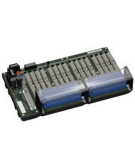

FC-GPCS-RIO16-PF Termination Board
Ask for price
- System board for Honeywell Safety Manager
- For 32-channel universal I/O card RUSIO-3224
- For 16 modules
- Recommended modules: HiC2025(A)(ES) (AI), HiC2031(ES) (AO), HiC2441 (UIO), HiC2831R2 (DI), HiC2853R2 (DI), HiC2871 (DO), HiC5861 (DO), HiC5863 (DO)
- Recommended system cable: CAB-HON-**-S37C32-MX-01000
- 24 V DC supply
- Hazardous area: pluggable screw terminals, blue
- Non-hazardous area: Sub-D connector (male), 37-pin
Description
Product Details
The function of the termination board and the connector pin assignment are exactly fitted to the requirements of the Honeywell system.
The signal is output to the safety instrumented system via the system connector.
Information about a missing supply voltage of the isolated barriers is available for the system as a volt-free contact.
It is possible to transfer a fault signal to channel 1 of the card via the loop-in function.
The termination board has a robust plastic housing.
The termination board is mounted in the switch cabinet on a 35 mm DIN mounting rail according to EN 60175.
Technical data
Supply
| Connection | TB3: terminals 2, 4(+); 1, 3(-) | |
| Nominal voltage | 24 V DC, in consideration of rated voltage of used isolators | |
| Voltage drop | 0.9 V, voltage drop across the series diode on the termination board must be considered | |
| Ripple | ≤ 10 % | |
| Fusing | 4 A, in each case for 16 modules | |
| Power dissipation | ≤ 500 mW, without modules | |
| Reverse polarity protection | yes |
Redundancy
| Supply | Redundancy available. The supply for the isolators is decoupled, monitored and fused. |
Fault indication output
| Connection | TB4: terminals 1, 2 | |
| Output type | volt-free contact | |
| Switch behaviour |
no fault: relay contact closed
power supply fault: relay contact open |
|
| Contact loading | 30 V DC, 1 A |
Indicators/settings
| Display elements |
LED Supply1 (power supply termination board), green LED
LED Supply2 (power supply termination board), green LED LED Error Status (fault indication), red LED LED lits: power supply fault |
Directive conformity
| Electromagnetic compatibility | |||||
|
|||||
Conformity
| Electromagnetic compatibility |
NE 21:2017
For further information see system description. |
|
| Degree of protection | IEC 60529:2001 |
Ambient conditions
| Ambient temperature | -20 … 60 °C (-4 … 140 °F) | |
| Storage temperature | -40 … 70 °C (-40 … 158 °F) |
Mechanical specifications
| Degree of protection | IP20 | |||||||||||||
| Connection | ||||||||||||||
|
||||||||||||||
| Core cross section | screw terminals: 0.25 … 2.5 mm2 (24 … 12 AWG) | |||||||||||||
| Material | housing: polycarbonate | |||||||||||||
| Mass | approx. 830 g | |||||||||||||
| Dimensions | 273 x 155 x 153 mm (10.7 x 6.1 x 6.0 inch) (W x H x D), depth including module assembly | |||||||||||||
| Mounting | on 35 mm DIN mounting rail acc. to EN 60715:2001 | |||||||||||||
Data for application in connection with hazardous areas
| EU-type examination certificate | CESI 06 ATEX 022 | ||||
|
|||||
| Non-hazardous area | |||||
|
|||||
| Certificate | DEMKO 18 ATEX 2116 X | ||||
|
|||||
| Galvanic isolation | |||||
|
|||||
| Directive conformity | |||||
|
|||||
International approvals
| UL approval | E106378 | |||||||
|
||||||||
| IECEx approval | ||||||||
|
||||||||
General information
| Supplementary information | Observe the certificates, declarations of conformity, instruction manuals, and manuals where applicable. For information see www.pepperl-fuchs.com. |