









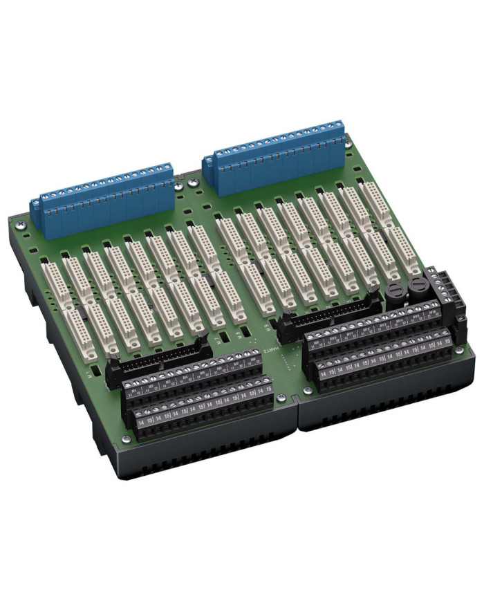

HiCTB16-SCT-44C-SC-RA Termination Board
Ask for price
- For 16 modules
- 24 V DC supply
- Supported signal types: DI/DO/AI/TI/AO/UIO
- Hazardous area: screw terminals, blue
- Non-hazardous area: screw terminals, black
Description
Product Details
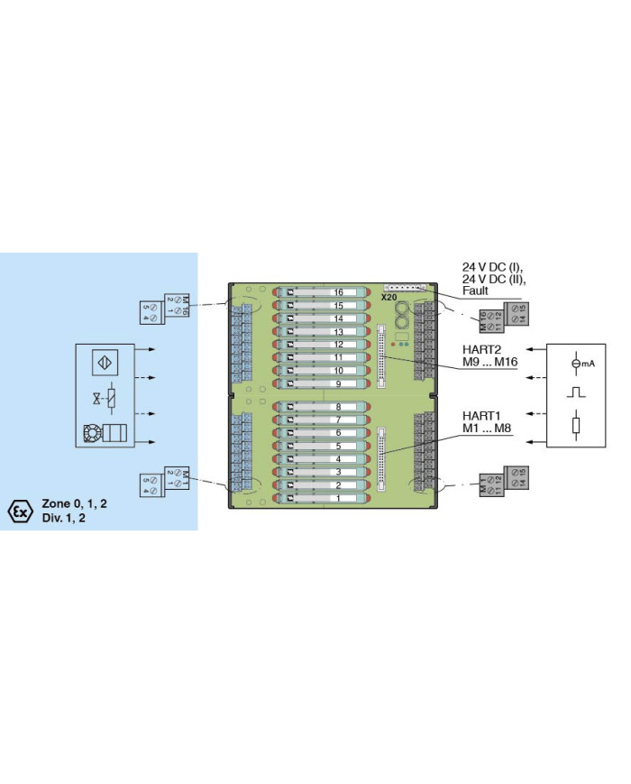
The termination board has 16 plugin slots for isolators. Any isolator can be inserted into any slot, enabling a mixture of I/O types on one termination board.
The termination board features fixed screw terminals for the field side connection and for the control side connection along with a HART cordset for interconnection to a separate HART Communication Board.
Information about missing supply voltage of the isolators is available for the system as volt-free contact at the redundant power supply terminals.
Wiring errors from field side will be reported via the same relay contact, if this function supported by the the isolators.
The termination board is supplied with a robust plastic housing as standard. This design permits the fast and reliable installation on 35 mm DIN mounting rail acc. to EN 60715 in the cabinet.
Technical data
Supply
| Connection | X20: terminals 3, 5(+); 4, 6(-) | |
| Nominal voltage | 24 V DC, in consideration of rated voltage of used isolators | |
| Voltage drop | 0.9 V, voltage drop across the series diode on the termination board must be considered | |
| Ripple | ≤ 10 % | |
| Fusing | 4 A, in each case for 16 modules | |
| Power dissipation | ≤ 500 mW, without modules | |
| Reverse polarity protection | yes |
Redundancy
| Supply | Redundancy available. The supply for the isolators is decoupled, monitored and fused. |
Fault indication output
| Connection | X20: terminals 1, 2 | |
| Output type | volt-free contact | |
| Switch behaviour |
no fault: relay contact closed
power supply fault: relay contact open module fault: relay contact open |
|
| Contact loading | 30 V DC, 1 A |
Indicators/settings
| Display elements |
LED PWR1 (termination board power supply), green LED
LED PWR2 (termination board power supply), green LED LED FAULT (fault indication), red LED LED lits: module fault LED flashes: power supply fault |
Directive conformity
| Electromagnetic compatibility | |||||
|
|||||
Conformity
| Electromagnetic compatibility |
NE 21:2017
For further information see system description. |
|
| Degree of protection | IEC 60529:2001 |
Ambient conditions
| Ambient temperature | -20 … 60 °C (-4 … 140 °F) | |
| Storage temperature | -40 … 70 °C (-40 … 158 °F) |
Mechanical specifications
| Degree of protection | IP20 | |||||||||||||
| Connection | ||||||||||||||
|
||||||||||||||
| Core cross section | screw terminals: 0.25 … 1.5 mm2 (24 … 12 AWG) | |||||||||||||
| Material | housing: polycarbonate, 10 % glass fiber reinforced | |||||||||||||
| Mass | approx. 860 g | |||||||||||||
| Dimensions | 216 x 200 x 163 mm (8.5 x 7.9 x 6.42 inch) (W x H x D), depth including module assembly | |||||||||||||
|
||||||||||||||
| Mounting | on 35 mm DIN mounting rail acc. to EN 60715:2001 | |||||||||||||
Data for application in connection with hazardous areas
| EU-type examination certificate | CESI 06 ATEX 022 | ||||
|
|||||
| Non-hazardous area | |||||
|
|||||
| Certificate | DEMKO 18 ATEX 2116 X | ||||
|
|||||
| Galvanic isolation | |||||
|
|||||
| Directive conformity | |||||
|
|||||
International approvals
| UL approval | E106378 | |||||||
|
||||||||
| IECEx approval | ||||||||
|
||||||||
General information
| Supplementary information | Observe the certificates, declarations of conformity, instruction manuals, and manuals where applicable. For information see www.pepperl-fuchs.com. |