










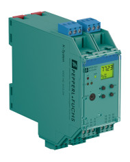

KFD2-HLC-Ex1.D.2W HART Loop Converter
Ask for price
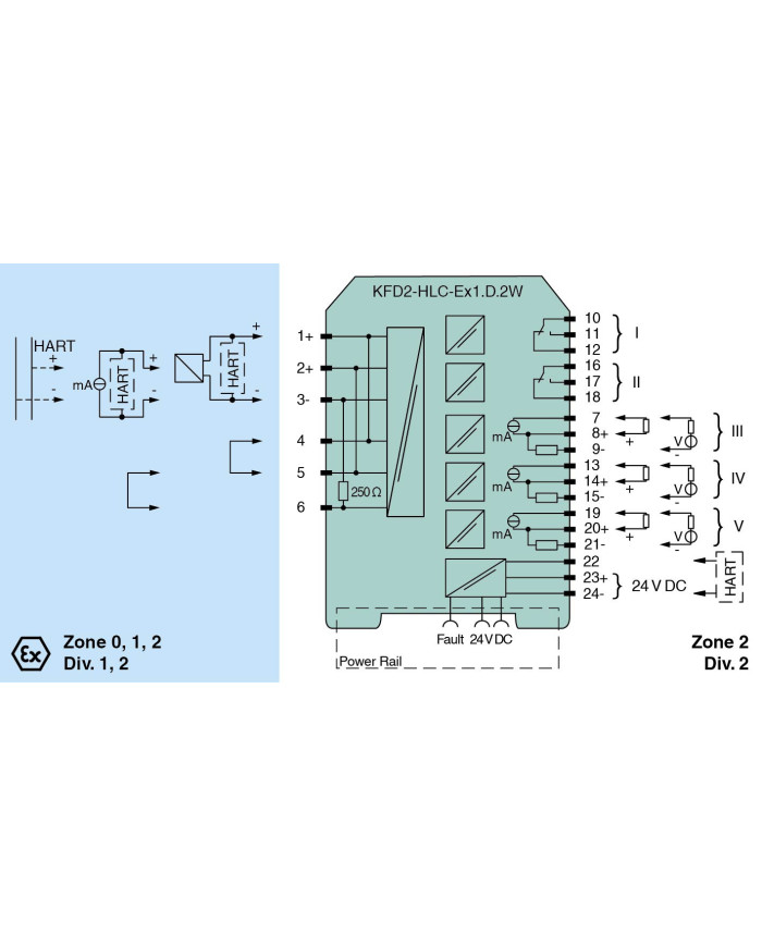
- 1-channel isolated barrier
- 24 V DC supply (Power Rail)
- HART field device input with transmitter power supply
- Usable as signal splitter (1 input and several outputs)
- 2 relay contact outputs (change-over contacts)
- 3 analog outputs 4 mA … 20 mA
- Sink and source mode output
- Configurable by keypad
Description
Product Details
This isolated barrier is used for intrinsic safety applications. It is a HART loop converter that provides power to transmitters or can be connected to existing HART loops in parallel.
It is able to evaluate up to four HART variables (PV, SV, TV, QV). Of those four HART variables, the data contained in any three of them can be converted to three different 4 mA … 20 mA current signals. These loop signals can be connected to display devices or analog inputs on the process control system/ control system.
In addition to the current outputs, two form C changeover relay contacts are available and can be programmed to operate at trip values from the HART variables.
The unit is easily programmed by the use of a keypad located on the front of the unit or with the PACTware configuration software.
For additional information, refer to the manual and www.pepperl-fuchs.com.
Technical data
General specifications
| Signal type | Analog input |
Supply
| Connection | Power Rail or terminals 23+, 24- | |
| Rated voltage | Ur | 19 … 30 V DC |
| Rated current | Ir | approx. 130 mA at 24 V DC |
| Power dissipation | 2.5 W | |
| Power consumption | 3.1 W |
HART signal channels (intrinsically safe)
| Conformity | HART field device input (revision 5 to 7) |
Interface
| Programming interface | programming socket |
Input
| Connection side | field side | |
| Connection | terminals 1, 2, 3, 4, 5, 6 | |
| Open circuit voltage/short-circuit current | typ. 24 V / 28 mA | |
| Input resistance | 250 Ω, 5 % (terminals 2, 3 and with jumper on 5, 6) | |
| Available voltage | ≥ 15.5 V at 20 mA, short-circuit protected |
Output
| Connection side | control side | ||||||||||||||||
| Connection |
output I: terminals 10, 11, 12, output II: terminals 16, 17, 18
output III: terminals 7, 8, 9, output IV: terminals 13, 14, 15, output V: terminals 19, 20, 21 |
||||||||||||||||
| Output I, II | |||||||||||||||||
|
|||||||||||||||||
| Output III, IV, V | |||||||||||||||||
|
|||||||||||||||||
| Other outputs | HART communicator on terminals 22, 24 | ||||||||||||||||
| Collective error message | Power Rail and LED red | ||||||||||||||||
Transfer characteristics
| Output III, IV, V | ||||||||||||||
|
||||||||||||||
| Relay | programmable either for fault or trip value (with direction, hysteresis and delay) | |||||||||||||
Galvanic isolation
| Output I/II | functional insulation acc. to IEC 62103, rated insulation voltage 250 Veff | |
| Output I, II/other circuits | reinforced insulation acc. to IEC 62103, rated insulation voltage 300 Vrms | |
| Output III/IV/V/power supply | functional insulation acc. to IEC 62103, rated insulation voltage 50 Veff |
Indicators/settings
| Display elements | LEDs, display | |
| Control elements | Control panel | |
| Configuration |
via operating buttons
via PACTware |
|
| Labeling | space for labeling at the front |
Directive conformity
| Electromagnetic compatibility | |||||
|
|||||
| Low voltage | |||||
|
|||||
Conformity
| Electromagnetic compatibility | NE 21:2006 | |
| Degree of protection | IEC 60529:2001 |
Ambient conditions
| Ambient temperature | -20 … 60 °C (-4 … 140 °F) |
Mechanical specifications
| Degree of protection | IP20 | ||||||||||
| Connection | screw terminals | ||||||||||
| Mass | 300 g | ||||||||||
| Dimensions | 40 x 119 x 115 mm (1.6 x 4.7 x 4.5 inch) (W x H x D), housing type C2 | ||||||||||
|
|||||||||||
| Mounting | on 35 mm DIN mounting rail acc. to EN 60715:2001 | ||||||||||
Data for application in connection with hazardous areas
| EU-type examination certificate | BASEEFA 07 ATEX 0174 | ||||||||||||||||||||||
|
|||||||||||||||||||||||
| Supply | |||||||||||||||||||||||
|
|||||||||||||||||||||||
| Equipment | terminals 1, 4/3 (with link between terminals 4 and 5) | ||||||||||||||||||||||
|
|||||||||||||||||||||||
| Equipment | terminals 2, 5/3 | ||||||||||||||||||||||
|
|||||||||||||||||||||||
| Output I, II | terminals 10, 11, 12; 16, 17, 18, non-intrinsically safe | ||||||||||||||||||||||
|
|||||||||||||||||||||||
| Output III, IV, V | terminals 7, 8, 9; 13, 14, 15; 19, 20, 21, non-intrinsically safe | ||||||||||||||||||||||
|
|||||||||||||||||||||||
| Certificate | PF 07 CERT 1141 X | ||||||||||||||||||||||
|
|||||||||||||||||||||||
| Galvanic isolation | |||||||||||||||||||||||
|
|||||||||||||||||||||||
| Directive conformity | |||||||||||||||||||||||
|
|||||||||||||||||||||||
International approvals
| FM approval | ||||||||
|
||||||||
| IECEx approval | ||||||||
|
||||||||
General information
| Supplementary information | Observe the certificates, declarations of conformity, instruction manuals, and manuals where applicable. For information see www.pepperl-fuchs.com. |