











HiATB01-FAULT-01 Fault Indication Board
Ask for price
- 1-channel
- 24 V DC supply
- Monitors up to 16 HiC Termination Boards
- Relay contact output
- LEDs for supply and fault status
Description
Product Details
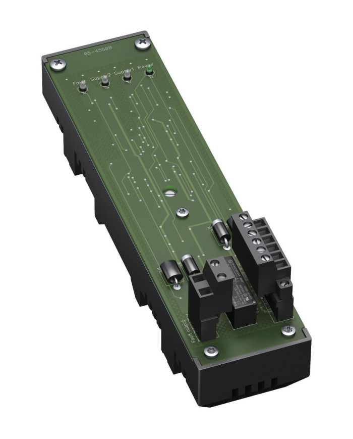
This Fault Indication Board is designed to monitor up to 16 H-System Termination Boards.
The fault bus signal can be wired in a ring (daisy chain) or redundant in a star.
Information about a missing supply voltage is available for the system as a volt-free contact.
The relay contact also signals a missing supply voltage at one of the monitored termination boards.
Wiring faults from the field side will be reported via the same relay contact, if this function supported by the the isolators.
The termination board is supplied with a robust plastic housing. This design permits the fast and reliable installation on 35 mm DIN mounting rail according to EN 60715 in the switch cabinet.
Technical data
Supply
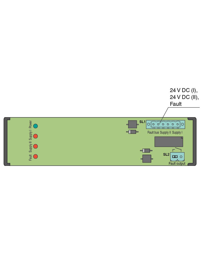
| Connection | SL1: terminals 3, 5(+); 4, 6(-) | |
| Rated voltage | Ur | 19.6 … 30 V DC |
| Ripple | ≤ 10 % | |
| Power dissipation | ≤ 500 mW | |
| Reverse polarity protection | yes |
Redundancy
| Supply | Redundancy available. The supply is decoupled and monitored. |
Fault indication output
| Connection |
fault bus (Fault) : SL1: terminals 1, 2
fault output : SL2: terminals 1, 2 |
|
| Output type | volt-free contact | |
| Switch behaviour |
no fault: relay contact closed
power supply fault: relay contact open module fault: relay contact open |
|
| Contact loading | 30 V DC, 1 A |
Indicators/settings
| Display elements |
LED Power (power supply), green LED
LED Supply I (missing supply I), red LED LED Supply II (missing supply II), red LED LED Fault (fault signal), red LED LED flashes: module fault/power supply fault at the termination board |
Directive conformity
| Electromagnetic compatibility | |||||
|
|||||
Conformity
| Electromagnetic compatibility |
NE 21:2017
For further information see system description. |
|
| Degree of protection | IEC 60529:2001 |
Ambient conditions
| Ambient temperature | -20 … 60 °C (-4 … 140 °F) | |
| Storage temperature | -40 … 70 °C (-40 … 158 °F) |
Mechanical specifications
| Degree of protection | IP20 | ||||||||||
| Connection | |||||||||||
|
|||||||||||
| Core cross section | screw terminals: 0.2 … 2.5 mm2 (24 … 12 AWG) | ||||||||||
| Material | housing: polycarbonate, 10 % glass fiber reinforced | ||||||||||
| Mass | approx. 165 g | ||||||||||
| Dimensions | 50 x 200 x 63 mm (1.97 x 7.9 x 2.48 inch) (W x H x D) | ||||||||||
|
|||||||||||
| Mounting | on 35 mm DIN mounting rail acc. to EN 60715:2001 | ||||||||||
General information
| Supplementary information | Observe the certificates, declarations of conformity, instruction manuals, and manuals where applicable. For information see www.pepperl-fuchs.com. |