










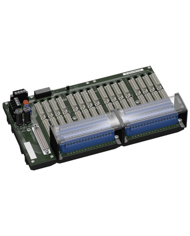
Brand:
Pepperl+Fuchs
- System board for Honeywell Safety Manager
- For 32-channel universal I/O card RUSIO-3224
- For 16 modules
- Recommended modules: HiC2025(A)(ES) (AI), HiC2031(ES) (AO), HiC2441 (UIO), HiC2831R2 (DI), HiC2853R2 (DI), HiC2871 (DO), HiC5861 (DO), HiC5863 (DO)
- Recommended system cable: CAB-HON-**-S37C32-MX-01000
- 24 V DC supply
- Hazardous area: pluggable screw terminals, blue
- Non-hazardous area: Sub-D connector (male), 37-pin
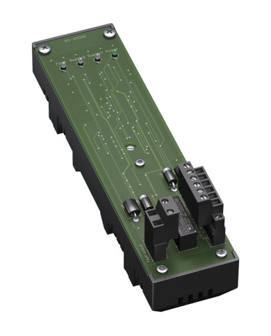
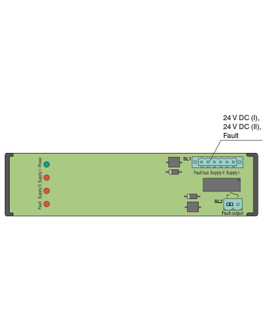
Brand:
Pepperl+Fuchs
- 1-channel
- 24 V DC supply
- Monitors up to 16 HiC Termination Boards
- Relay contact output
- LEDs for supply and fault status
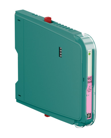
Brand:
Pepperl+Fuchs
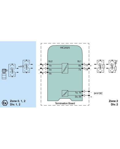
- 1-channel isolated barrier
- 24 V DC supply (bus powered)
- Input for 2-wire SMART transmitters and current sources
- Output for 4 mA … 20 mA or 1 V … 5 V
- Low power dissipation
- Up to SIL 2 (SC 3) acc. to IEC/EN 61508

Brand:
Pepperl+Fuchs
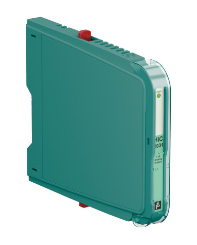
- 1-channel isolated barrier
- 24 V DC supply (bus powered)
- Current output up to 650 Ω load
- Low power dissipation
- Up to SIL 2 (SC 3) acc. to IEC/EN 61508

Brand:
Pepperl+Fuchs
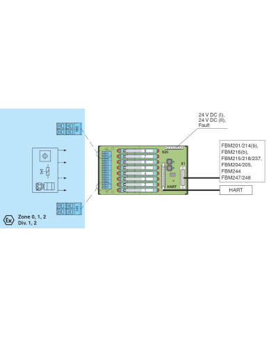
- System board for Schneider, Foxboro FBM series
- For 8 modules
- For 8-channel cards FBM201/214(b)/216(b) (AI), FBM215/218/237 (AO), FBM204/205 (AO/AI), FBM244 (AI/AO), FBM247/248 (UIO)
- 24 V DC supply
- Recommended modules: HiC2025(A) (AI), HiC2031 (AO), HiC2081 (TI), HiC2831R5 (DI), HiC2883 (DO), HiC2441 (UIO)
- Hazardous area: spring terminals, blue
- Non-hazardous area: Sub-D connector (male), 25-pin

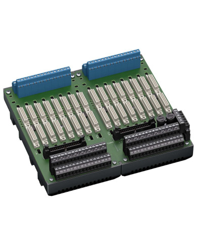
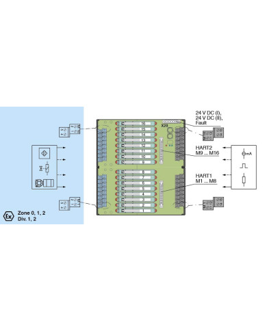
Brand:
Pepperl+Fuchs
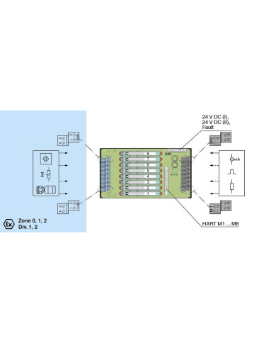
- For 8 modules
- 24 V DC supply
- Supported signal types: DI/DO/AI/TI/AO/UIO
- Hazardous area: screw terminals, blue
- Non-hazardous area: screw terminals, black
Brand:
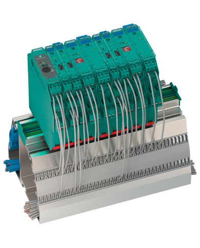
Pepperl+Fuchs
- For 16 modules
- 24 V DC supply
- Supported signal types: DI/DO/AI/TI/AO/UIO
- Hazardous area: screw terminals, blue
- Non-hazardous area: screw terminals, black
Brand:
Pepperl+Fuchs
Profile rail with UPR-03- * insert, 3 conductors, wiring comb field side, blue
- Cable trunking with integrated Power Rail UPR-03
- Safe spacious separation of safe and hazardous signals
- No additional cable guides necessary
- Provides DC supply voltage to all equipped K-System modules
- Standard length 1.8 m (5.8 ft), simple to customize to application space
- With end caps UPR-E, cover and mounting aids

Brand:
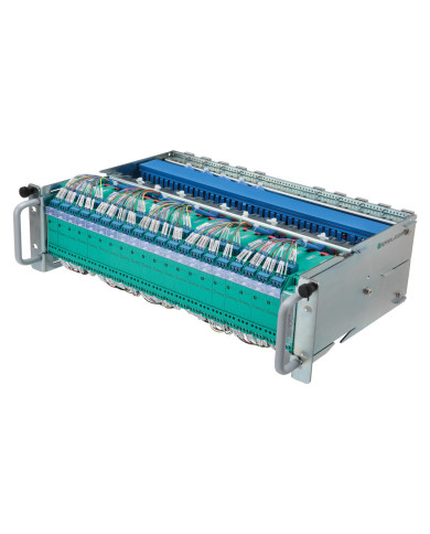
Pepperl+Fuchs
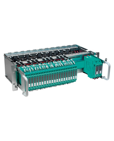
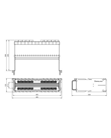
- Subrack for K-System
- Replacement for subrack of the E-System
- Max. 33 slots for isolators
- Long design (300 mm mounting depth)
- Connection via marshalling patchboards
- With middle sheet and cable duct
- Partial and combined assembly possible
- Complete wiring according to customer requirements
- Allows to retain cable routing in the switch cabinet
- No structural changes on the switch cabinet required
Brand:
Pepperl+Fuchs
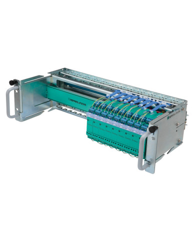
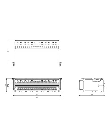
- Subrack for K-System
- Replacement for subrack of the E-System
- Max. 33 slots for isolators
- Long design (300 mm mounting depth)
- Connection via marshalling patchboards
- Partial and combined assembly possible
- Complete wiring according to customer requirements
- Allows to retain cable routing in the switch cabinet
- No structural changes on the switch cabinet required
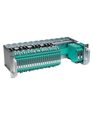
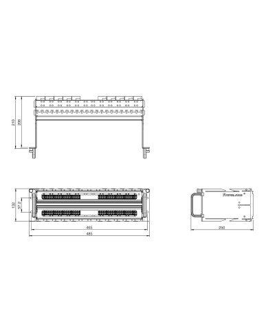
Brand:
Pepperl+Fuchs
- Subrack for K-System
- Replacement for subrack of the E-System
- Max. 33 slots for isolators
- Short design (211 mm mounting depth)
- Connection via terminal blocks
- Partial and combined assembly possible
- Complete wiring according to customer requirements
- Allows to retain cable routing in the switch cabinet
- No structural changes on the switch cabinet required
Brand:
Pepperl+Fuchs
- Subrack for K-System
- Replacement for subrack of the E-System
- Max. 33 slots for isolators
- Short design (211 mm mounting depth)
- Connection via marshalling patchboards
- Partial and combined assembly possible
- Complete wiring according to customer requirements
- Allows to retain cable routing in the switch cabinet
- No structural changes on the switch cabinet required
Brand:
Pepperl+Fuchs
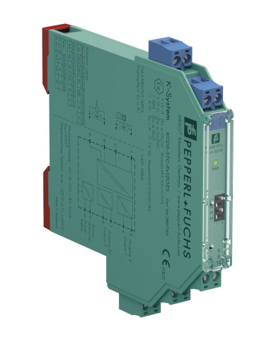
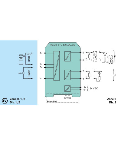
- 1-channel isolated barrier
- 24 V DC supply (Power Rail)
- Input for 2-wire SMART transmitters and current sources
- Signal splitter (1 input and 2 outputs)
- Dual output 0/4 mA … 20 mA or 0/1 V … 5 V
- Terminal blocks with test sockets
- Up to SIL 3 acc. to IEC/EN 61508
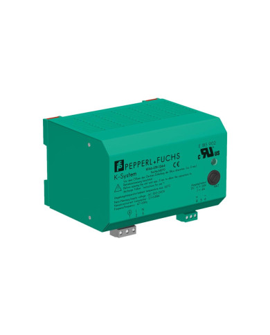
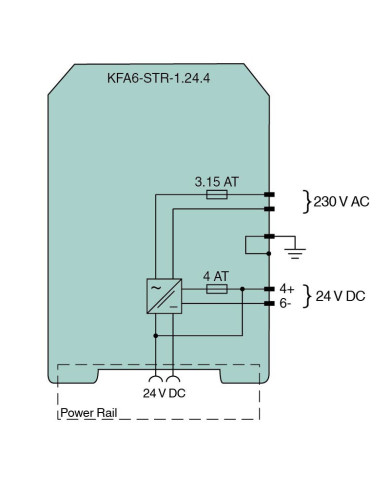
Brand:
Pepperl+Fuchs
Electric power supply; removable terminals; supply voltage 92 V … 265 V AC; output voltage 24 V DC, 4 A; suitable for Power Rail supply
- 115/230 V AC supply
- Output 24 V DC, 4 A
- Fused output
- Power Rail connection
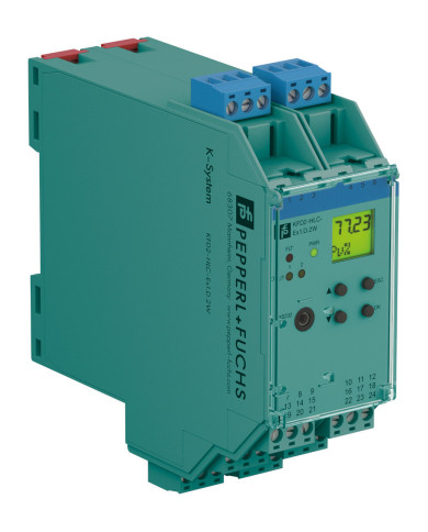
Brand:
Pepperl+Fuchs
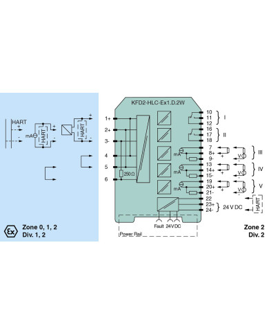
- 1-channel isolated barrier
- 24 V DC supply (Power Rail)
- HART field device input with transmitter power supply
- Usable as signal splitter (1 input and several outputs)
- 2 relay contact outputs (change-over contacts)
- 3 analog outputs 4 mA … 20 mA
- Sink and source mode output
- Configurable by keypad
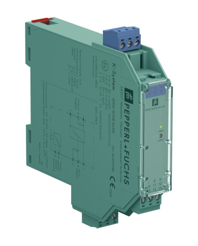
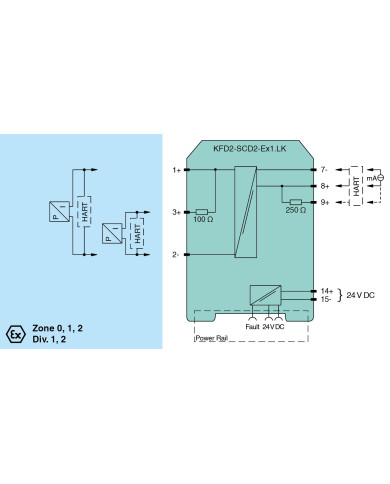
Brand:
Pepperl+Fuchs
- 1-channel isolated barrier
- 24 V DC supply (power rail)
- Current output up to 650 Ω load
- HART-IP and valve positioner
- Line fault detection (LFD)
- Accuracy 0.1 %
- Up to SIL 2 (SC 3) acc. to IEC/EN 61508
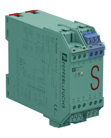
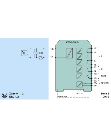
Brand:
Pepperl+Fuchs
- 1-channel isolated barrier
- 24 V DC supply (Power Rail)
- Input for approved dry contacts or SN/S1N sensors
- Relay contact output
- Fault indication output
- Line fault detection (LFD)
- Up to SIL 3 acc. to IEC/EN 61508
- Up to PL d acc. to EN/ISO 13849

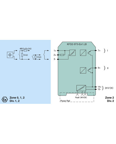
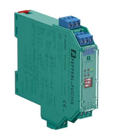
Brand:
Pepperl+Fuchs
- 1-channel isolated barrier
- 24 V DC supply (power rail)
- Dry contact or NAMUR inputs
- 2 active transistor outputs
- Usable as signal splitter (1 input and 2 outputs)
- Reversible mode of operation
- Line fault detection (LFD)
- Up to SIL 2 (SC 3) acc. to IEC/EN 61508
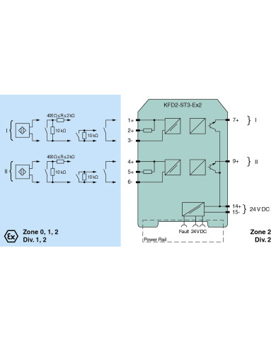
Brand:
Pepperl+Fuchs
- 2-channel isolated barrier
- 24 V DC supply (Power Rail)
- Dry contact or NAMUR inputs
- Active transistor output
- Line fault detection (LFD)
- Reversible mode of operation
- Up to SIL 2 (SC 3) acc. to IEC/EN 61508
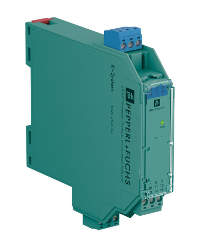
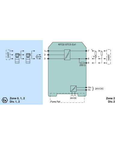
Brand:
Pepperl+Fuchs
- 1-channel isolated barrier
- 24 V DC supply (power rail)
- Input 2-wire and 3-wire SMART transmitters and 2-wire SMART current sources
- Output 4 mA … 20 mA current sink/current source
- Terminals with test points
- Up to SIL 2 acc. to IEC/EN 61508
Brand:
Pepperl+Fuchs
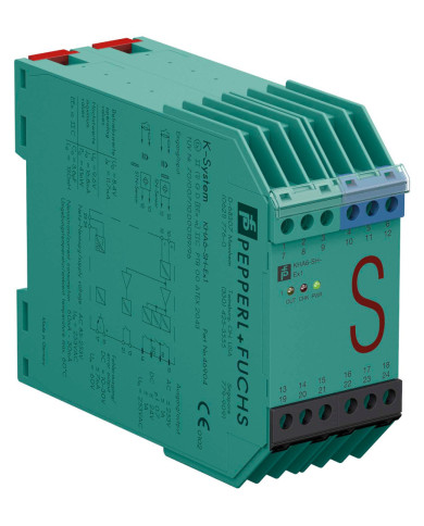
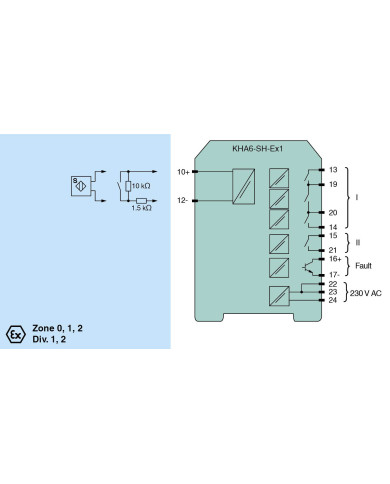
- 1-channel isolated barrier
- 115/230 V AC supply
- Input for approved dry contacts or SN/S1N sensors
- Relay contact output
- Fault indication output
- Line fault detection (LFD)
- Up to SIL 3 acc. to IEC/EN 61508
- Up to PL d acc. to EN/ISO 13849
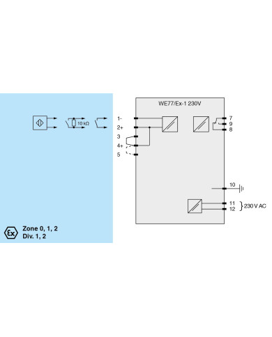
Brand:
Pepperl+Fuchs
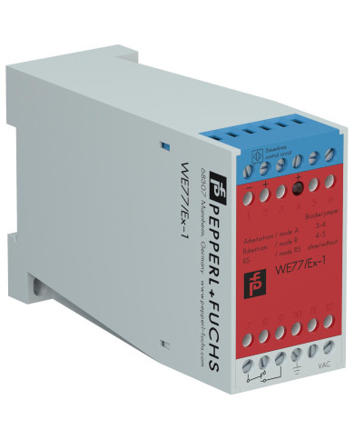
- 1-channel
- Control circuit EEx ia IIC
- 230 V AC supply voltage
- Reversible mode of operation
- Lead breakage (LB) monitoring
- 1 relay contact output (change-over contact)